Chapter 0 : What is Error Correcting Code?
Error correcting code is a technology to correct errors that occur in transmission lines. Error correcting codes are used in various transmission paths such as wired/wireless internet using PCs, data communication using mobile phones, one-segment TV, and storage devices such as HDD and Blu-Ray.
In this section, we will explain what an error correcting code is in the following chapters in an easy-to-understand manner.
Chapter 1 : Principles of Error Correcting Codes
Error correcting codes are a technology to correct errors that occur in transmission lines by adding redundancy to the information to be transmitted. Figure 1-1 shows specific examples of coding and decoding.
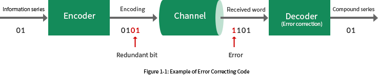
The encoder adds redundant bits to the information sequence. The decoder corrects bit errors that occur in the communication channel. The decoder corrects the errors using the added redundant bits. The principle of error correction is extremely mathematical, and it takes a lot of time to understand the theory in depth, but Figure 1-2 shows a diagram that explains it in a visually easy-to-understand manner. As a concrete example, Fig. 1-2 shows an error-correcting code that adds two bits of redundancy to two bits of information.
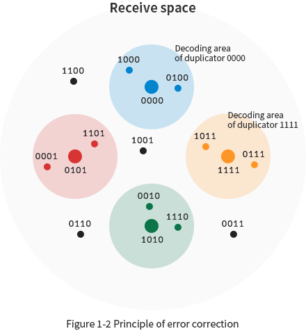
Figure 1-2 shows the receive space, which in this example is a 4-bit vector space. There are 16 points in this vector space, and four of these points (0000, 0101, 1010, 1111) correspond to the correct code word. When these points are received, the decoder determines that no error has occurred. The process performed by the decoder when the other 12 points are received can be divided into the following two cases.
| Case 1 | When a point in the decoding domain of each code word is received → Correct 1-bit errors and restore each code word |
|---|---|
| Case 2 | When a point outside the decoding domain is received → Determine that an uncorrectable error has occurred |
From the standpoint of the system receiving the decoded sequence, the success or failure of error correction can be classified into the three categories shown in Table 1-1. Since the decoder cannot distinguish between "correctable" and "error correction," it is necessary to introduce an error detection code (e.g., CRC) separately when the distinction is necessary.
Table 1-1 Error correction results
| OK with corrections (printing) | Description |
|---|---|
| Amendable | When the received word enters the decoding area of the transmitted code word |
| Miscorrection | If the received word enters the decoding area of a code word different from the transmitted code word |
| Uncorrectable (Error detection) | If the received word does not enter the decoding area of any code word |
※Supplement 1-1
Error correcting codes used for explanation add redundant bits to the information sequence. Thus, a code in which the information sequence is represented in the code word in its original form is called an organizational code. Although organizational codes are often used as error correction codes, there are error correction codes that are not organizational codes.
※Supplement 1-2
The error correcting code used for the explanation is not exactly a 1-bit error correcting code. This is because it cannot correct all 1-bit errors. For example, if we consider the case where a one-bit error occurs when the code word 0000 is transmitted, it can be corrected when 1000 or 0100 is received, but it will be erroneously corrected when 0010 or 0001 is received.
※Supplement 1-3
Error correcting codes used for explanation are codes that process in bit units, but there are also error correcting codes that process in symbol units, such as Reed-Solomon codes. Reed-Solomon codes can be constructed by considering any number of bits as one symbol.
Chapter 2 : Error Correcting Capabilities of Error Correcting Codes
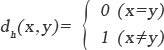
The correction capability of an error correcting code can be considered using the Hamming distance The definition of the Hamming distance dh between two symbols is shown in Equation 2-1. That is, the Hamming distance between the same symbol is 0 and the Hamming distance between different symbols is 1.
【Equation 2-1】
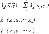
The definition of the Hamming distance dh between two n-dimensional vectors is shown in Equation 2-2. From Equation 2-2, the Hamming distance between two vectors is equal to the number of different symbols.
【Equation 2-2】
As a concrete example of Hamming distance, Table 2-1 shows the Hamming distance of any two different code words for a code with four vectors (0000,0101,1010,111) as code words.
Table 2-1 Examples of Hamming distance
| Code word 1 | Code word 2 | Hamming distance |
|---|---|---|
| 0000 | 0101 | 2 |
| 0000 | 1010 | 2 |
| 0000 | 1111 | 4 |
| 0101 | 0000 | 2 |
| 0101 | 1010 | 4 |
| 0101 | 1111 | 2 |
| Code word 1 | Code word 2 | Hamming distance |
|---|---|---|
| 1010 | 0000 | 2 |
| 1010 | 0101 | 4 |
| 1010 | 1111 | 2 |
| 1111 | 0000 | 4 |
| 1111 | 0101 | 2 |
| 1111 | 1010 | 2 |
From Table 2-1, we can see that the minimum distance between any two different code words of this code is 2. This is called the minimum distance dmin of the code. The correction capability of an error correcting code can be expressed using the minimum distance. The necessary and sufficient condition for correcting all the errors with less than t codes is shown in Equation 2-3.
【Equation 2-3】

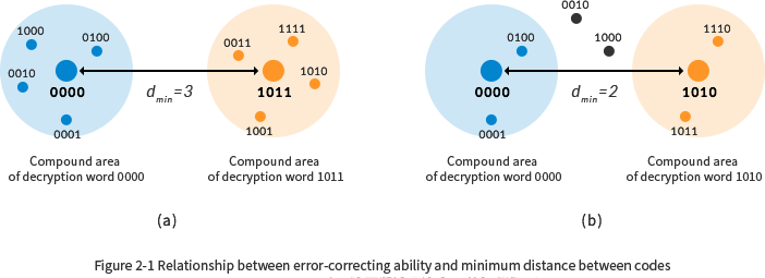
From Equation 2-3, the minimum distance must be greater than 3 to correct one error. This is easy to understand if we consider Figure 2-1. (a) shows the case where the minimum distance is 3, and all vectors with distance 1 from each code word can be included in the decoding area. Therefore, all 1 errors can be corrected. (b) shows the case where the minimum distance is 2, and all vectors with distance 1 from each code word cannot be included in the decoding area. This is because vectors 0010 and 1000 have distance 1 from both code words 0000 and 1010. Therefore, it is not possible to correct all 1 errors.
※Supplement 2-1
The Hamming distance and correction capability have been described for the case where a symbol is a single bit, but the same applies to the case where a symbol is multiple bits.
※Supplement 2-2
The error "detection" capability can also be expressed using the minimum distance. The necessary and sufficient condition for detecting all errors with t or less signs is shown in Equation 2-4.
【Equation 2-4】

Chapter 3 : Selection of Error Correction Codes
There are various types of error correcting codes such as Hamming codes and Reed-Solomon codes. Their characteristics differ depending on the code, such as codes that can be implemented with a small circuit size and codes that have a correction capability close to the theoretical limit. Therefore, it is necessary to select the most appropriate error correcting code according to the characteristics of the error to be generated and the requirements of the application.
Even if it is decided to use Reed-Solomon codes, it is necessary to consider what degree of correction capability is optimal. For example, consider the application of Reed-Solomon codes with 8 bits per symbol to the communication as shown in Table 3-1.

The block error rate Pb without error correcting code can be calculated as in Equation 3-1 using N and Ps. It can be seen that the block error rate Pb deviates significantly from the block error rate P that we want to guarantee.
【Equation 3-1】
If a Reed-Solomon code with an error correction capability of T symbols per block is applied to this communication, the block error rate Pc after error correction can be calculated using Equation 3-2. C in the equation represents the combination. The result of the relationship between the number of corrected symbols T and the block error rate Pc using Equation 3-2 is shown in Fig. 3-1. From Fig. 3-1, it can be seen that to achieve the block error rate P to be guaranteed, a Reed-Solomon code with a number of correction symbols T of 5 should be used.
【Equation 3-2】
However, the above method for determining the number of correction symbols has a major problem. This is because it does not take into account the fact that the amount of information that can be transmitted is reduced by the amount of redundant symbols added by the Reed-Solomon sign. While it is important for the application to achieve a guaranteed block error rate, it is equally important to achieve a target rate of information transmission. How can we apply Reed-Solomon codes while maintaining the rate at which information is transmitted? One solution is to increase the transmission rate. In the case of Reed-Solomon with T=5, the number of redundant symbols added is 10. Therefore, the transmission rate can be maintained by increasing the communication speed by a factor of 128/118. When the communication speed is increased, it is normal that the symbol error rate Ps generated in the communication channel worsens. Considering this, the relationship between the number of corrected symbols T and the block error rate Pc draws a curve as shown in Fig. 3-2. By selecting the minimum number of corrected symbols that can achieve the block error rate to be guaranteed, the desired performance can be obtained with the minimum circuit size.
Every system has an optimal error correction code and its correction capability. In order to find the optimal solution, it is necessary to comprehensively consider the information transmission rate, power, LSI cost, and information transmission environment (noise environment, etc.), and it is often uncertain whether the optimal solution has really been selected.
Siglead Inc. provides a service to propose the optimal solution. The company can propose not only existing error correcting codes but also Siglead's original error correcting codes. In combination with the contract design service, Siglead can propose not only high-speed, low-power and area-saving circuits, but also a total solution including the peripheral circuits of error correcting codes.
※Supplement 3-1
The symbol error rate can be calculated as "number of incorrect symbols/total symbols transmitted".
The block error rate can be calculated as "number of wrong blocks/total blocks transmitted".
※Supplement 3-2
Equation 3-2 can be used to calculate the block error rate after error correction using Reed-Solomon codes, but the equation assumes that the symbol errors that occur in the communication channel are completely random. In the actual communication channel, symbol errors often occur in bursts, and in most cases the block error rate deviates greatly from the result obtained by Equation 3-2. To calculate the block error rate correctly, it is necessary to observe the burst characteristics of symbol errors that occur in the communication channel and calculate the error rate using a more complex formula.
Siglead also provides a service to verify and select the most suitable error correcting code for a specific system. We propose the most effective error correcting code among several error correcting codes including not only existing error correcting codes but also Siglead original error correcting codes. We can also provide total solution including peripheral circuits by combining with commissioned design service.
Please contact our representative for more information.