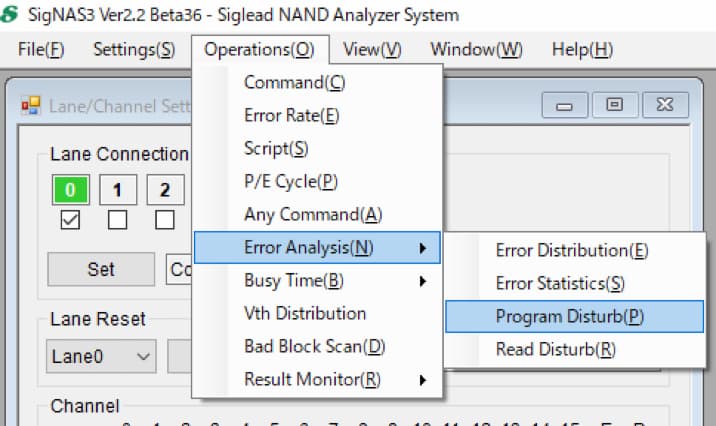
Evaluation of error P/E cycle dependence
Last time, we introduced the P/E cycle, and now we will introduce the ability of SigNAS3 to measure the errors that occur in relation to this stress.
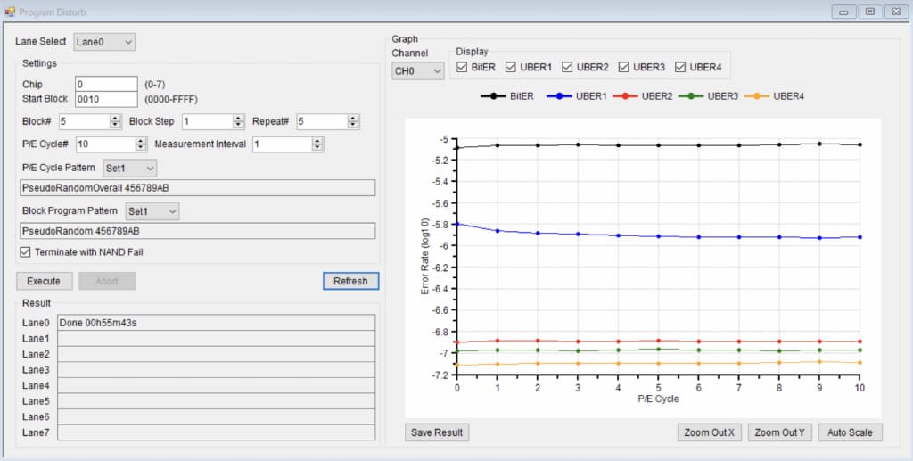
Program Disturb
This is a phenomenon in which the threshold voltage of unselected cells and transistors that share a word line increases due to programming operations.
As a result, the data cannot be read correctly, resulting in an error.
The probability of occurrence increases as the number of rewrites increases.
SigNAS3's Error Analysis function measures the P/E cycle dependence of the bit error rate and the error rate after ECC.
Configure ECC in General Settings. (Introduced in the error checking section of Read Data)
Lane Select
Select the connected lane in the Lane/Channel Settings window.
Settings
Set the measurement conditions using the following parameters.
Chip
Set the chip number (CE) from 0 to 7.
Start Block
Set the block number to start the measurement as a 4-digit hexadecimal number (maximum value FFFF).
Block#
Set the number of blocks to mesure.
Block Step
Set the block step (increment) when performing the measurement.
For example, when Start Block is 0010, Block# is 5, and Block Step is 4, execute measurement for blocks 0010, 0014, 0018, 001C, and 0020.
Repeat#
Set the number of times ProgramDisturb measurement is repeated per block.
For example, if you set it to 5, the series of erase, program, and read operations will be repeated 5 times.
P/E Cycle#
Set the number of P/E cycle executions.
Measurement Interval
Set the interval for error rate measurement until the number of times set in P/E Cycle# is reached.
For example, if P/E Cycle# is set to 10000 and Measurement Interval is set to 1000,
the error rate will be measured when the P/E number is 0, 1000, 2000, … 9000, 10000.
P/E Cycle Pattern
Select and set the block program pattern to be used during P/E cycle execution from Sets 1 to 5.
When selected, the pattern name set in Pattern Setting (previously introduced) will be displayed.
Block Program Pattern
Select and set the block program pattern used for error rate measurement from Sets 1 to 5.
When selected, the pattern name set in Pattern Setting (previously introduced) will be displayed.
Terminate with NAND Fail
If checked, if an error occurs due to NAND etc. during P/E cycle execution, execution will stop at that point.
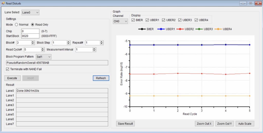
Read Disturb
Repeated read operations cause the threshold voltage of unselected cell transistors (Bit Line direction, different Word Line) in the same memory cell array to rise.
As a result, the data cannot be read correctly, resulting in an error.
This problem can be solved by erasing the unselected cells/transistors.
The SigNAS3 function measures the P/E cycle dependence of the bit error rate and the error rate after ECC.
Configure ECC in General Settings. (Introduced in the error checking section of Read Data)
Lane Select
Select the connected lane in the Lane/Channel Settings window.
Settings
Set the measurement conditions using the following parameters.
Mode
Normal: Performs a series of erase, program, and read operations.
Read Only: Read only.
Chip
Set the chip number (CE) from 0 to 7.
Start Block
Set the block number to start the measurement as a 4-digit hexadecimal number (maximum value FFFF).
Block#
Set the number of blocks to mesure.
Block Step
Set the block step (increment) when performing the measurement.
For example, when Start Block is 0010, Block# is 5, and Block Step is 4, Execute measurement for blocks 0010, 0014, 0018, 001C, and 0020.
Repeat#
Set the number of times the measurement is repeated per block.
or example, if you set 5, the series of operations according to the Mode setting will be repeated 5 times.
Read Cycle#
Set the number of times Read is executed.
Measurement Interval
Set the interval for error rate measurement until the number of times set in ReadCycle# is reached.
For example, if Read Cycle# is set to 10000 and Measurement Interval is set to 1000,
the error rate will be measured when the number of reads is 0, 1000, 2000, … 9000, 10000.
Block Program Pattern
Select and set the block program pattern used for error rate measurement from Sets 1 to 5.
When selected, the pattern name set in Pattern Setting (previously introduced) will be displayed.
Terminate with NAND Fail
If checked, if an error occurs due to NAND etc. during P/E cycle execution, execution will stop at that point.
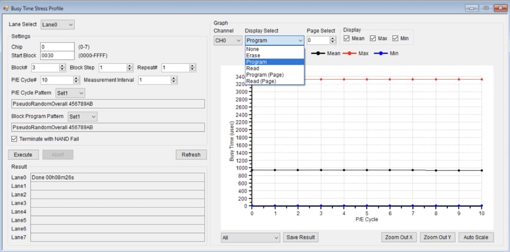
Busy Time Stress Profile
BusyTime measurement was previously introduced. It is an indicator of NAND performance and quality.
Below, we will introduce the SigNAS3 GUI function that measures the P/E Cycle dependence of Busy Time.

Lane Select
Select the connected lane in the Lane/Channel Settings window.
Settings
Set the measurement conditions using the following parameters.
Chip
Set the chip number (CE) from 0 to 7.
Start Block
Set the block number to start the measurement as a 4-digit hexadecimal number (maximum value FFFF).
Block#
Set the number of blocks to mesure.
Block Step
Set the block step (increment) when performing the measurement.
For example, when Start Block is 0010, Block# is 5, and Block Step is 4, Execute measurement for blocks 0010, 0014, 0018, 001C, and 0020.
Repeat#
Set the number of times Busy Time measurement is repeated per block.
For example, if you set it to 5, the series of erase, program, and read operations will be repeated 5 times.
P/E Cycle#
Set the number of P/E cycle executions.
Measurement Interval
Set the interval for error rate measurement until the number of times set in P/E Cycle# is reached.
For example, if P/E Cycle# is set to 10000 and Measurement Interval is set to 1000, the error rate will be measured when the P/E number is 0, 1000, 2000, … 9000, 10000.
P/E Cycle Pattern
Select and set the block program pattern to be used during P/E cycle execution from Sets 1 to 5.
When selected, the pattern name set in Pattern Setting (previously introduced) will be displayed.
Block Program Pattern
Select and set the block program pattern used for error rate measurement from Sets 1 to 5.
When selected, the pattern name set in Pattern Setting (previously introduced) will be displayed.
Terminate with NAND Fail
If checked, if an error occurs due to NAND etc. during P/E cycle execution, execution will stop at that point.