Vth Distribution measurement
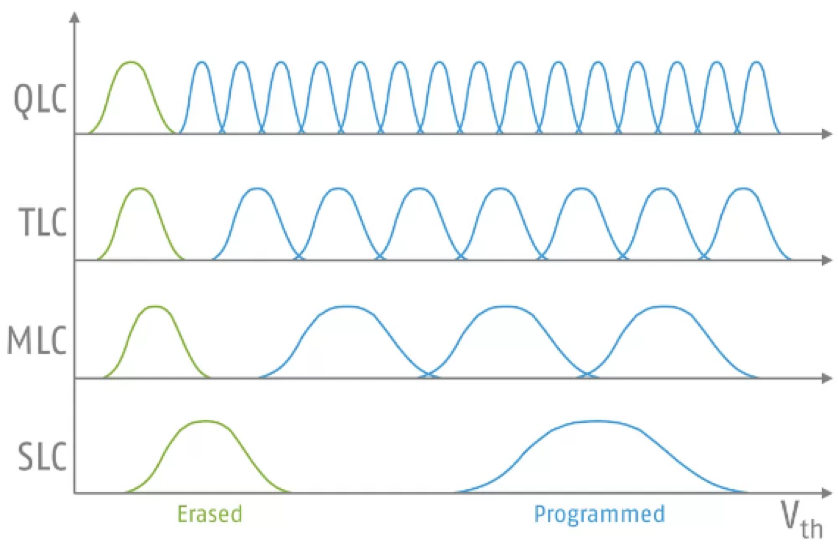
NAND flash memory (NAND) technology is advancing toward multi-value recording (recording three or more values in a single memory cell) to improve storage capacity, and QLC (Quad Level Cell) is currently being put to practical use.
For example, the memory method of TLC (Triple-Level Cell) is 3 bits/cell, 8 levels of threshold voltage (program is 7 levels).
The greater the number of values recorded, the more it is necessary to finely control the threshold voltage and repeat the verification during both programming and reading, so it becomes conspicuous that the time required for each operation (latency) tends to increase and deterioration tends to be accelerated (endurance is shortened).
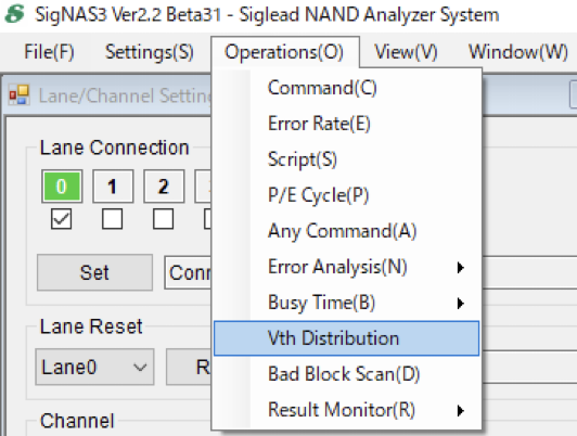
SigNAS3 is equipped with a Vth Distribution measurement function for quality evaluation based on these characteristics.
Measurement example of TLC NAND
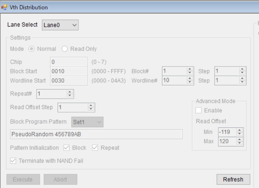
Setting parameters
Word Line: In the case of TLC, it consists of 3 pages (Lower, Middle, Upper).
For example, when measuring the Vth distribution of TLC, check the NAND structure with the datasheet, etc. for the values of Wordline Start and Wordline#, and set values that do not fall into the SLC or MLC area.
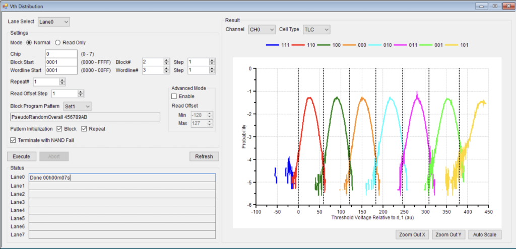
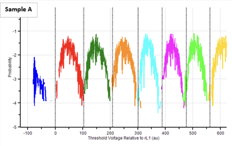
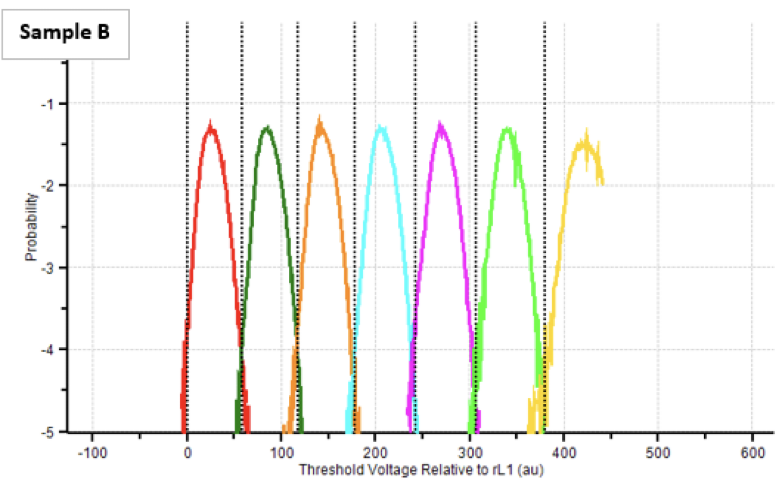
Measurement result graph
The plotted value is the average value for all measurements
X-axis
Relative value unit (au: arbitrary unit) based on the voltage difference rL1 (read level 1) when reading the erased state (111) and the next programmed state (011, although it varies depending on the manufacturer) is displayed.
Y-axis
Proportion of cells at the voltage within its read voltage range at each programmed value
As shown in the figure below, there are differences in the characteristics of samples from different manufacturers.
For NAND for which detailed datasheets are not available, SigNAS3 does not support this feature and the parameters shown in the figure below cannot be set.
Please consult with us in that case.