Busy Time (Operation time) measurement
The time required for each operation (Erase, Program, Read) for NAND Flash Memory (NAND) is called Busy Time, and it is one of the performance indicators that affect the performance of the final product.
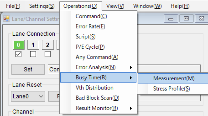
SigNAS3 has its measurement function in GUI and Script.
First, an example of Busy Time measurement with GUI is shown below.
The measurement sample chip in this example is 3D-TLC.
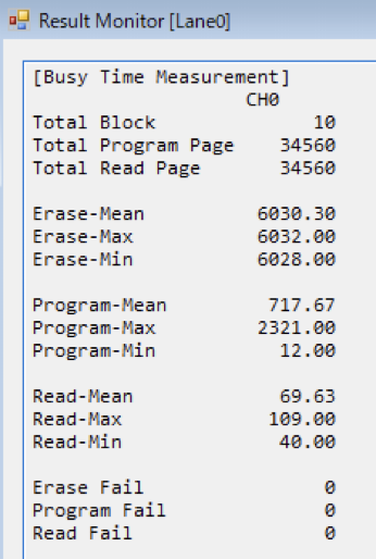
Measurement results for 10 blocks from the 20th block.
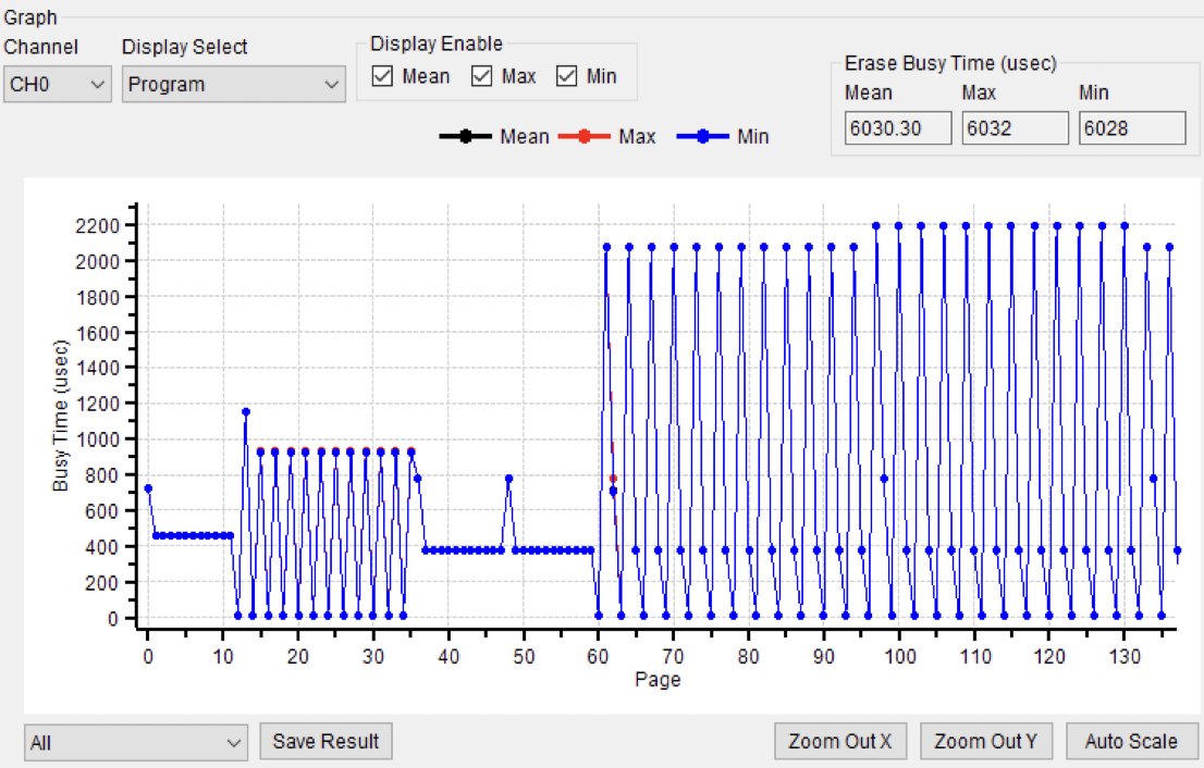
X-axis: Page number, Y-axis: Busy Time[μs]
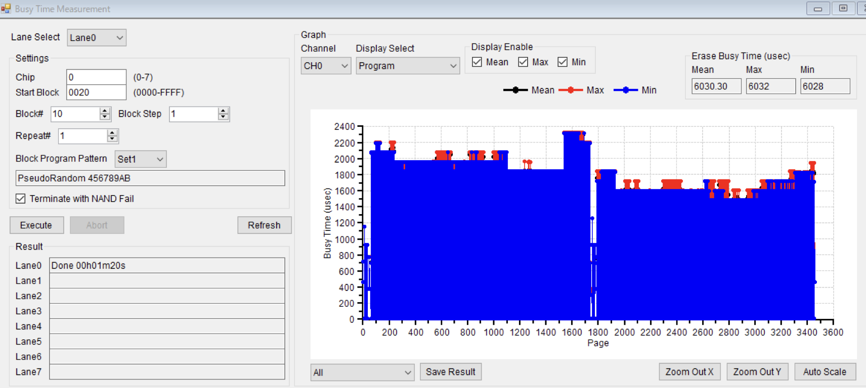
Display of Result Monitor
Program BusyTime (Zoom in)
BusyTime of Read (Zoom in)
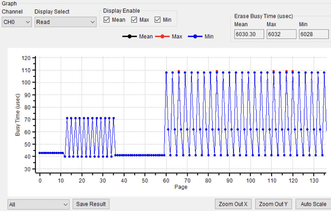
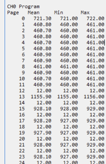
The results in the figure above show the features of the internal structure of NAND.
Block configuration
The above results show that not all areas are TLC, but there are SLC, MLC, and TLC areas.
Cell (page) configuration
MLC consists of Lower and Upper, and TLC consists of Lower, Middle, and Upper, and each BusyTime is clearly different.
This is because actual programming and reading are performed in units of 2 pages for MLC and 3 pages for TLC.
There is almost no time difference for each cell of the same structure.
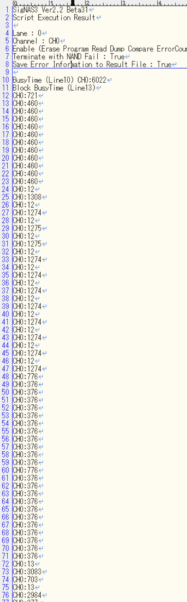
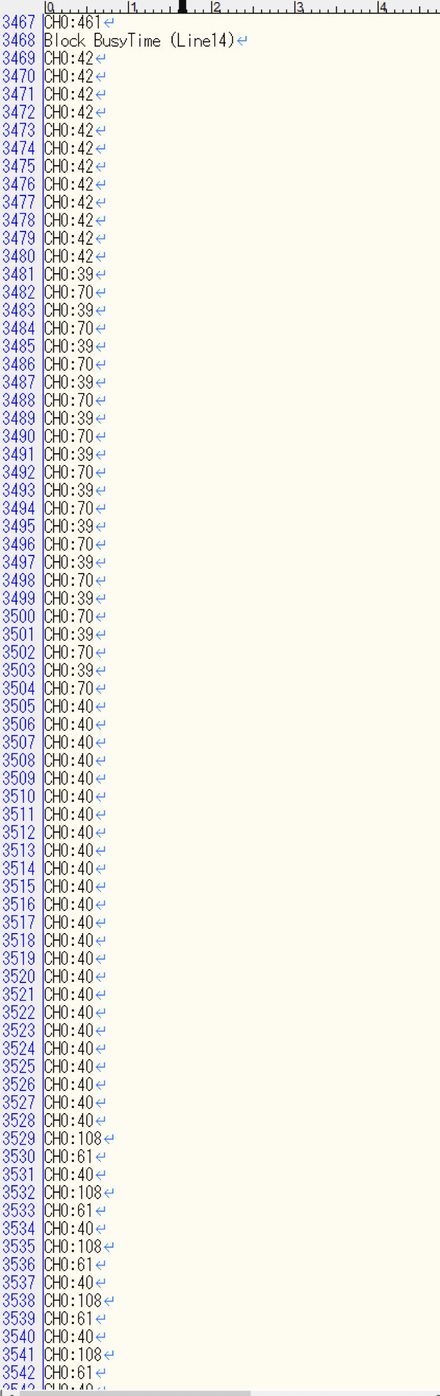
Measurement by Script
BusyTime is measured when issuing a command (Erase, Program, Read) to NAND.
By setting the parameter of the following command to 1 in advance and issuing it, it will be saved in the Result File.
BUSYTM、BKBSTM、CMBSTM
For each command, please refer to OperationManual for the target command of BusyTime saving.
Script
- 'Busy Time Measurment
- 'Block
- VSET04 0 0000
- 'Page
- VSET04 1 0000
- BUSYTM 1
- BKERAS 0 $V04_00$
- BKBSTM 1
- BKPROG 0 $V04_00$ RDMOVL 456789AB
- BKRDEC 0 $V04_00$ RDMOVL 456789AB
- PGREAD 0 $V04_00$ $V04_01$
Result File